Product details
We use DC Motors in many systems in our day to day life. For example, CPU fans, fume extinguishers, toy cars etc. are all DC Motors that are operated by DC power supply. Most of the time we will have to adjust the speed of the motors as per our requirement.
A CPU Fan, for example, must be operated at high speed when the CPU is performing heavy tasks like games or video editing. But for normal usage like editing documents, the speed of the fan can be reduced. Although some systems have an automatic adjustment system for fan speed, not all systems possess this functionality. So, we will have to adjust the speed of the DC Motor ourselves occasionally.
In this circuit, the DC motor is operated by a 555 integrated circuit. TheIC 555 in this circuit is being operated in astable mode, which produces continuous HIGH and LOW pulses. In this mode, the 555 IC can be used as a pulse width modulator with a few small adjustments to the circuit. The frequency of operation of the circuit is provided by the passive parameters of resistances and capacitors attached to it.
Pinout:
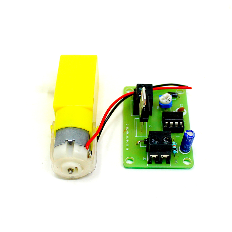
 Pin 1 of 555 is connected to GND. Pins 8 and 4 are connected to +V
Supply.- Pins 6 and 2 are short and a 100nF Capacitor is connected between Pin
2 and GND. The wiper pin of the POT is connected to Pin 3 of 555. Two
Schottky diodes (1N5819) are connected to the other two pins of the
POT as shown in the circuit diagram. - The common point of the diodes is connected to Pin 2. Pin 7 is pulled
high with the help of a 10KΩ Resistor. The Gate terminal of the MOSFET
is connected to Pin 7 of 555. The motor is connected between +12V
Supply and Drain of MOSFET while the Source of MOSFET is connected
to GND.
Application:
- To control the speed of the motor efficiently.
Package Include:
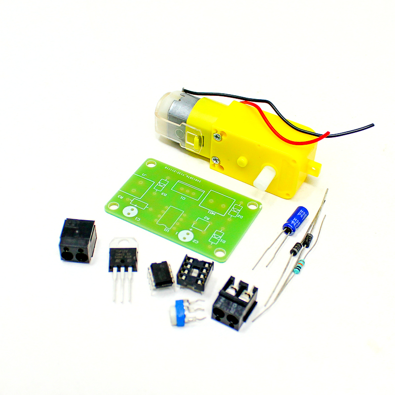
1 x Orange DIY LM555 Based Motor Speed Controller


There are no reviews yet.